GL Profiles Bracket and Bar System, for New Twin wall and Roof Envelopes & GL Profiles Refurb System
The GL Techbar marks the evolution of the support bar system and is set to become the first choice for supporting twin envelope systems & built up refurbishment systems.
FEATURES
- Four ribs offer superior strength and greater pullout performance
- Position markers on every bar to assist with Bracket Spacings
- Bar to bar connecting for extra strength and stability
- Advancements in galvanising result in higher quality components
- Thermal check-pad also creates air seal to liner
- May be fitted vertically for horizontal cladding
- Standard and bespoke range of bracket and bar sizes
BENEFITS
- Faster yet more accurate to assemble, easy to fix in place
- More cost effective, reliable and safer to use
- Advancements in the engineering and production process have increased the quality, strength, stability and durability
- Extensive technical support service including design and consultation
- Product has been independently tested

Support bar innovation
The launch of the GL Techbar marks a new and innovative time for the concept of the support bar system. Used for both new build and refurbishment applications, the high performance design and enhanced features of the GL Techbar system offers the roofing and cladding industry a far superior solution. Whether for a new build or refurbishment, for metal cladding of walls and roofs it provides the complete energy efficient solution, designed to surpass the latest building regulations.
Standard bracket heights (mm)
100, 110, 120, 130, 140, 150, 160, 170, 180, 190, 200, 210, 220, 230, 240, 250, 260, 270, 280, 290, 300
(other heights can be produced by arrangement).

SUPPORT BAR
With the increased number of ribs for higher strength. Manufactured from high quality 1.25mm galvanised steel to EN10147. Available in lengths of 1.2m and 3m from stock. Other lengths available by arrangement.
BRACKET
Improved design and added ribs mean increased strength. Manufactured from 1.60mm galvanised steel to EN10147, with vapour seal pad/thermal insulator. Heights available from 60mm to 280mm. Additional heights available by arrangement.
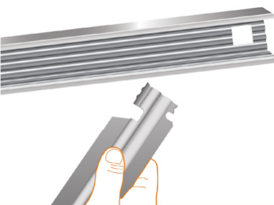
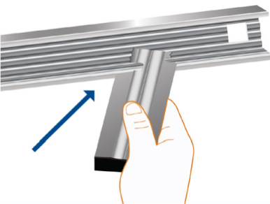
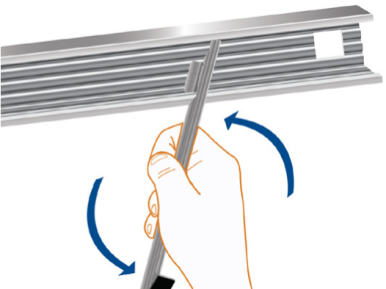
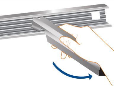
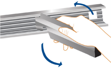
SIMPLE ASSEMBLY
Advancements in production facilities mean better insulation. Engage the lower bracket tab into the bar at the required location. Twist the bracket to engage the upper tab into the bar and continue twisting to lock the bracket into place.

GL TECHBAR GUIDE TO INSTALLATION
The GL Techbar has been designed to surpass the ever increasing demands of building regulations (Parts ADL 1 & 2 but also with a view to adding the installer during the often-hazardous construction stage.
The construction phase is the most dangerous and the health and safety of the installer has become a major factor in the design. From the connecting ends to the improved design of the actual bar and bracket, the safety of the installers is at the forefront of our design.
BASIC FIXING PROCEDURE
Install profiled lining sheets to the structural purlins/rails with self-drilling fasteners; ensure that the liners are sealed correctly to obtain effective air movement control. For refurbishing older roofs, treat the old top sheet as the liner, and fit the new roof over the top.
GL Techbar brackets are twist-locked into the Techbar at intervals of approx. 1 metre to suit the liner profile. The locating guide that is printed on each bar will assist with the setting out at regular intervals. A bracket should be positioned within 100mm of the bar end joint. The assembly is positioned on the roof with the long 40mm leg of the bar facing upslope towards the ridge and fixed through the bracket base and liner and into the purlin with two self-drilling fasteners per bracket.
Insulation, when required, is rolled out on to the liner, dressing around the bracket and under the bars to achieve continuous cover. (For Firewall applications this procedure differs, technical data available upon request) The top sheets are laid onto the and fastened down, using the self- drilling fasteners.
VERTICAL
The sheeting rail spacing and building design will dictate the position of the bars, which must be supported on a structural member. For further information on vertical installation, please contact our technical support department.
VERTICAL SHEETING ON GL TECHBAR
Using the GL Techbar spanning along principle cladding rails with brackets at 1.0m and 1.2m enables the cladding contractor to quickly and efficiently install vertical claddings.
The GL Techbar brackets are twisted into the support bar at the appropriate centres – 1.0m to 1.2m – aided by the bracket location guide permanently marked on every bar. The completed assembly is then offered up to the liner panels and fixed using two self-drilling screws through each bracket.
With typical cladding rail centres at 1.8m and brackets spaced at 1.2m centres, service wind loads in excess of 1.0kN/m2 can be resisted. Insulation is fitted under the GL Techbar system and secured using self-adhesive stickpins except where fire conditions dictate a more robust fixing detail.
The bracket foot is insulated from the liner panel / cladding rail via the thermal break pad on its underside, which also assists in achieving satisfactory air seal continuity.

Horizontal Sheeting on Top-hats
We have also developed an innovative top-hat system for spanning vertically across the cladding rails to support horizontal sheeting. These vertical bars can be made continuous by using splice joints. The top-hats are fixed on to bespoke TechWall Brackets with two self drilling fasteners (one per side). The TechWall Brackets are then fixed to the sheeting rail with two or more self drilling fasteners. This detail superbly distributes vertical load over all the sheeting rails. The TechWall vertical top-hat system provides excellent structural performance. With a general wind loading of 1kN/m2 and typical rail centres of 1800mm, the TechWall system requires vertical top-hats at 1400mm c/c.
Depending upon wind, loading bars can be as far apart as 3000mm.
The support bar system allows insulation quilt to be laid with the minimal compression under the and around the brackets. It includes a thermal break on the base bracket to minimise cold bridging and energy loss.
Using typical twin skin components, it will meet the requirements of the building regulations – Part L2 – without difficulty. Brackets, being well spaced out across the roof, do not cause significant cold bridging.
HORIZONTAL SHEETING ON GL TECHBAR
The GL Techbar has been designed for vertical application of horizontal wall cladding with bracket depths up to 140mm and rail centres up to 2000mm apart. To achieve a safe working load of 1kN/m2 using GL Techbar in multiple spans across the cladding rails, spaced at 2000mm in relation to the overall height of the building, it may be necessary to fix the GL Techbar at 600mm centres along the wall. However, it must be noted that the extended length of brackets may result in some deflection of the cladding. Whilst the GL Techbar twist and lock system results in a good interference fit, in vertical applications it is necessary to provide additional anti-sag measures to prevent excessive deflections. When the fitted system is supported at suitable intervals, it ensures that the weight of the cladding is transferred to the structure. Solutions available include supporting the base of the bar on a structural steel member, or fixing to a top-hat or simple cleat to stabilise the bar in addition to standard brackets to the cladding rail.
Note: For sheeting rail centres up to 1800mm, the GL Techbar system can be fitted as illustrated but attention must be paid to loads and deflections. Contact our technical department for further information regarding spacing of the GL Techbar.

Note: For sheeting rail centres up to 1800mm, the GL Techbar system can be fitted as illustrated above but attention must be paid to loads and deflections. Contact our technical department for further information regarding spacing of the GL Techbar.

Note: For sheeting rail centres up to 1800mm, the GL Techbar system can be fitted as illustrated above but attention must be paid to loads and deflections. Contact our technical department for further information regarding spacing of the GL Techbar.
Fire Wall Standards Approved Document B, Volume 2
(As amended, 2022), furthermore referred to as ADBv2
The objective of the firewall is to act as a barrier to stop the spread of fire and rigorous testing is carried out to ascertain how long it can retain its stability. The regulations state limits for how long the wall must remain stable and how long the insulation must restrain the heat coming through the wall. This is important to enable people to evacuate a building safely.
Building Regulations define clearly the minimum fire safety requirements of building elements/requirements in two ways.
Reaction to fire
Reaction to fire relates to the degree to which a product will contribute, by its own decomposition, to a fire under specified conditions.
In simple terms, reaction to fire is the materials characteristic of how quickly it promotes flame spread.
Fire resistance
Fire resistance is the ability of an item to fulfill for a stated period of time the required fire stability and/or integrity and/or thermal insulation, and/or other expected duty specified in a standard fire resistance test. A fire resistance test is a test where a fully developed fire is simulated inside a prescribed furnace and the item (e.g., wall, or floor) is subjected to the test. In the case of walls, the ability of containing the fire is measured in minutes. Failure is defined when cracks appear enabling passage of flames or hot gases.
| Performance | Fire tests | Classification in accordance with |
| Reaction to fire | Recommended essential testing.
EN 13823, and EN ISO 11925-2 |
BS EN 13501-1 |
| Fire resistance | BS EN 1364-1 | BS EN 13501-2 |
Fire Roof Standards Approved Document B, Volume 2
GL Profiles Ltd. are seeking the system performance to be permissible on buildings with separation distance of less than 6m, those would require performance of Broof(t4), as per Table 14.1.
There are at least two methods of demonstrating the performance classification:
- By undertaking fire testing and classification per BS EN 13501-5, or
- Roof covering products falling under the scope of Classification Without Further Testing
LOAD TABLES

ASSEMBLY GUIDE
Advancements in production facilities mean better installation. Engaged the lower bracket tab into the bar at the required location. Twist the bracket to engage the upper tab into the bar and continue twisting to lock the bracket into place.
Movement 1
Movement 2
Movement 3
Movement 4
Movement 5
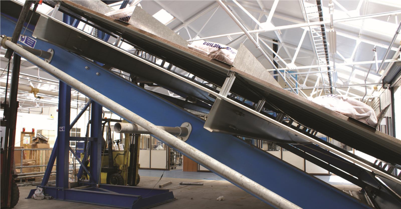
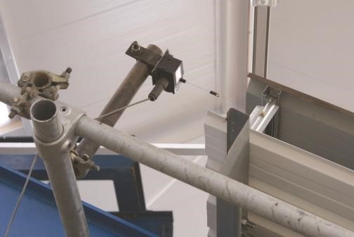
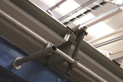
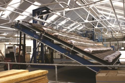
GL Techbar being tested at Ceram Test House in accordance with industry procedures
Picture19
Picture18
Picture17